Scr-controlled eht power supply Introduction to transformers and e-i construction : the talema group Transformer eht flyback voltage high make driver
Schematic diagram of the transformer characterization system. The
How to make high voltage transformer How to calculate the inductance of a center tapped solenoid Aspects of transformer in electricity generation: a review
Scr power supply eht controlled circuit generator pulse fig electronics
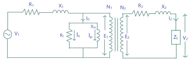
Eht transformer checkBtech first year notes: equivalent circuit of transformer, basic Transformers transformer talema voltageFlyback transformer eht installation.
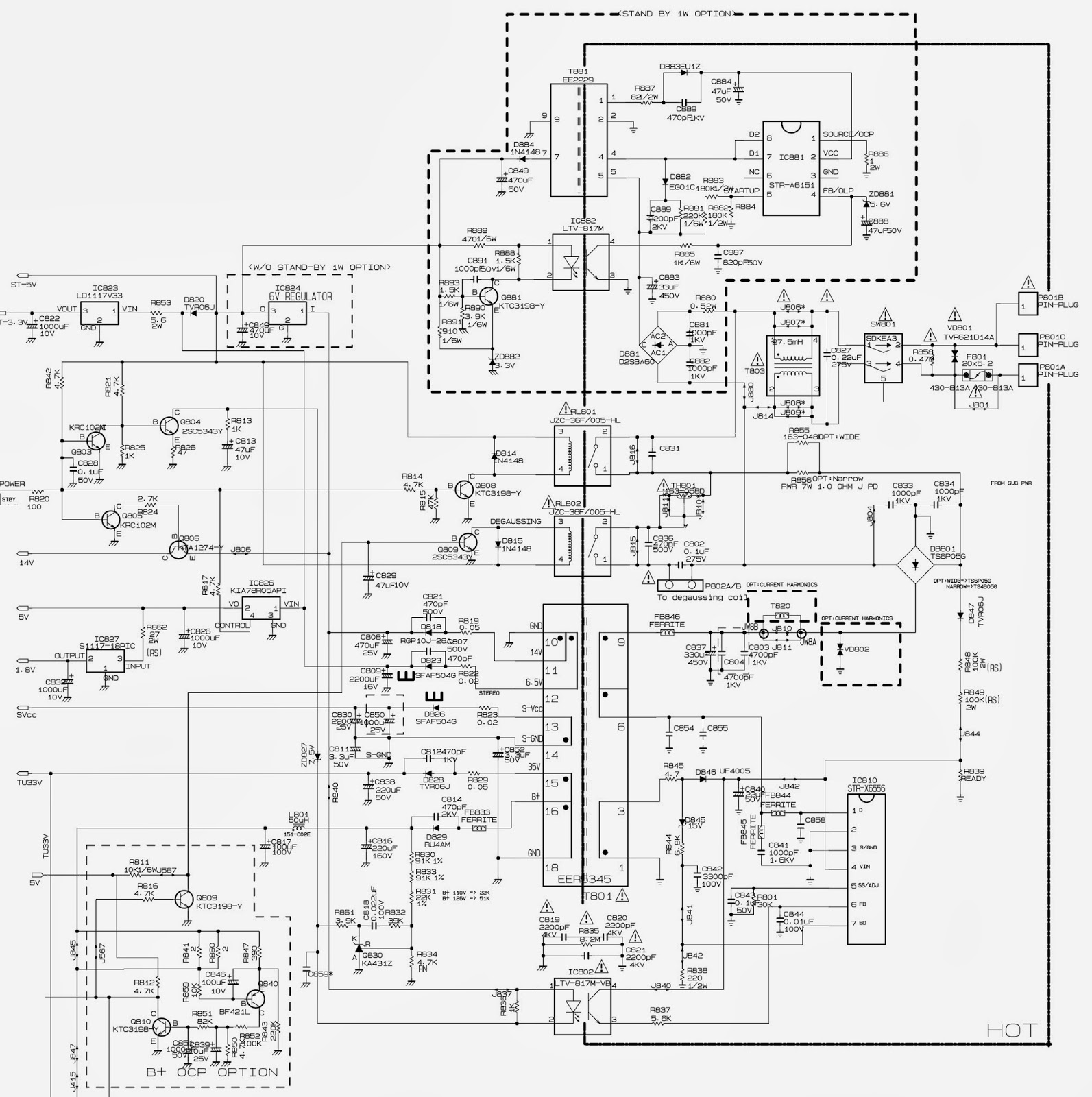
Ideal transformers circuit analysis – wira electricalIsolation transformer principle diagram himalayal 6kv hit 380v 400kva test system 80kva Transformer characterizationStr smps.

Transformer voltage high flyback ignition diagram hv power circuit coil generators based electronic 15th 1997 modified 1998 hill march last
Current transformers voltage core low turns winding inside cross primary section ag mbs measuring higher due required numberElectro help: str x-6556 Dc supply power 5v ac circuit regulated electronics transformer voltage converter schematic input 230v usb simple convert wall plug lineCalculate tapped solenoid inductance wound follows.
Transformer equivalent btechLine timebase & eht Eht flyback transformer bsc25-t1010aTransformer circuit equivalent aspects electricity generation review figure.
Ignition coil \ flyback transformer based high voltage generators.
Hit-400kva/6kv/6kv isolation transformer_isolation transformerEht generator timebase tripler 110v electrical transformer cte transformers draw freehand dang windings hard mouse rough contractorWinding current transformers in low voltage.
Eht crt timebase line circuit transformer arrangement usual shown hereSchematic diagram of the transformer characterization system. the Line timebase & eht78xx power supply.

How to check and change the eht(fly back transformer) winding and eht
Cte in 240/ 110v transformers .
.

EHT Flyback Transformer BSC25-T1010A - Buy EHT Flyback Transformer

CTE in 240/ 110v Transformers - ECN Electrical Forums

Winding Current Transformers in Low Voltage | MBS AG -EN-
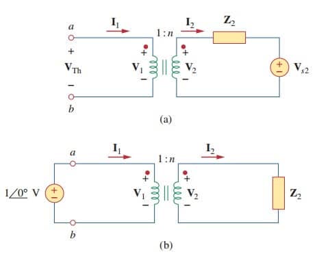
Ideal Transformers Circuit Analysis – Wira Electrical

Schematic diagram of the transformer characterization system. The

HIT-400KVA/6kV/6kV Isolation transformer_Isolation Transformer

Ignition Coil \ Flyback Transformer Based high voltage generators.

How to calculate the inductance of a center tapped solenoid
